I’m currently enrolled in a course to learn more about refrigeration systems. I program the MACS Cooler, which is a sophisticated, automatic produce cooler. During our last class, one of the instructors drew a block diagram of the basic refrigeration system (like what runs a refrigerator) on the white board.
I furiously copied the diagram in my notes on my tablet with OneNote. I added color where I thought it helped. Later, I used Inkscape to recreate the diagram as a digital graphic. And here it is.
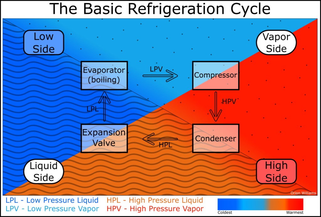
The Basic Refrigeration Cycle
Evaporation
Starting with LPL (Low Pressure Liquid), the refrigerant goes out to the evaporator coil. The evaporator is a heat exchanger, taking heat out of the air and putting it into the refrigerant. This heat makes the refrigerant boil (evaporate) into a LPV (Low Pressure Vapor).
Compression
Next, the evaporated refrigerant, which is now a vapor (gas), moves to the compressor. The compressor pumps the vapor up to a high pressure. Now it is a HPV (High Pressure Vapor).
Condensation
The HPV travels to the condenser where another heat exchange happens. This time, the heat of the refrigerant is moved to the condenser cooling medium (air/water). During this heat exchange, the vapor changes state to a liquid (condensing) but remains a high pressure (HPL – High Pressure Liquid).
Expansion
As the HPL passes through an expansion valve (i.e. a metering valve), it rapidly expands due to the low pressure that the compressor is creating on that side of the valve. Upon expanding, the refrigerant gives up its heat. Now we are back to a Low Pressure Liquid.